After getting most of the smaller components rebuilt and ready to go on the car, I started the longer term phase of rebuilding major mechanical sub components around October 2004 and hope to be complete by about December.
Most garage restorers avoid getting into complex units like differentials, however I wanted to change my finial gear ratio from 3.54:1 to 3.07:1 because I found that the stock 3.54 ratio made first gear completely useless. The 3.8Liter XK engine with 3 SU's has plenty of torque to start even in second gear, and first gear winds up to 3500 RPM before 20 mph. I also found that highway speeds of 70+ were obtained in top gear running over 3000 rpm and the top speed with this ratio at red line would be around 120mph vs the more exciting 140+ which the 3.07 produces. I also didn't like the idea of leaving 40 year old bearings and clutch packs in alone in a car which had clearly had a hard life.
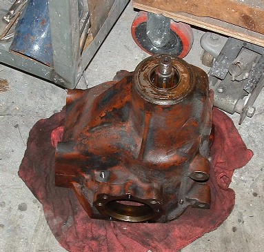
This is what I had after I shelled the differential. I found that several bad things had been going wrong which made the tear down well warranted. The output shaft flanges had been setup incorrectly the past and about 1/8" of metal had been ground off of side. The shims which were installed to set the end float on these shafts were mangled and over time the unit would have most likely had a catastrophic failure. I also found that clutch pack on one side had several cracked plates. This was most likely caused by the incorrect forces starting at the output shafts, or just general use and abuse.
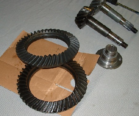
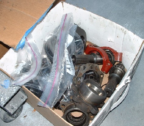
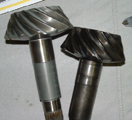
The next order of business after tear down was sourcing parts! Finding ring and pinion gears and bearings for a 40 year old differential is easier than you'd think. The Jaguar IRS is based on a common Dana 44 gear set. These ring and pinion sets are still being produced and are commonly found on Jeep Cherokee's and Ford light duty trucks. Dana makes ratios from 3.07:1 up to about 4:1. I found a good online source for gear and bearing sets. (Reider Racing). The ring and pinion was about $160 and the Bearing set was another $150. Unfortunately the bearings aren't all the same so some extra parts had to be found elsewhere.
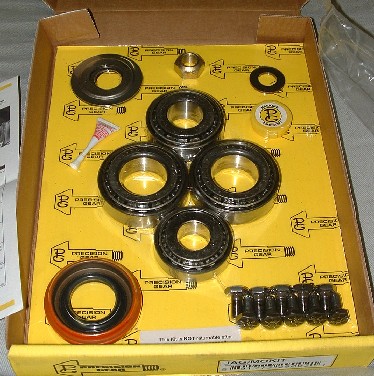
Here is the install kit for the new ring and pinion. It includes all seals bearings and bolts to install to a modern Jag IRS less the output shafts. I also found that the outer pinion bearing wasn't correct. Guess it is to much to ask that Jaguar continue using the exact same bearings for over 40 years. This shortage forced me to find another source for bearings who could take original Timken bearing and race numbers and source parts. I used "International Bearing" a mail order (non online) company. Located here in Northern CA. They had no trouble finding any of the parts I needed! Prices were generally cheaper than the usual Jaguar suppliers and I could specify Timken vs other bearing makes.
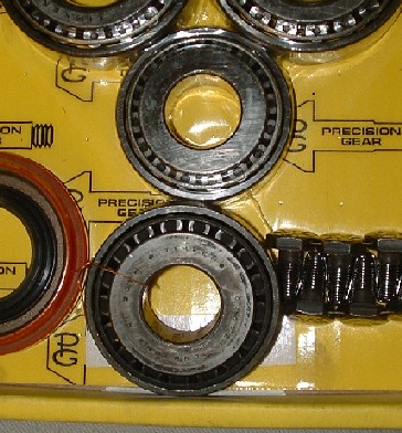
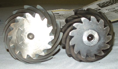
Here is the original outer pinion bearing along side the part from the kit. The inside diameter is correct but the outside on the old bearing is about .250" larger than the one in the kit. The replacement roller and race cost about $50.
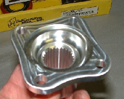
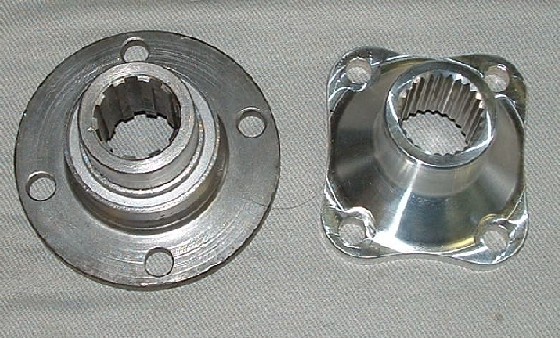
Here is said flange. It doesn't look anything like the original, but has the same bolt pattern and the correct tooth to fit the new pinion. I was a little worried about it being Aluminum instead of steel, but this part was made by a shop that specializes in AC Cobra Kit cars, so I assume if it can take the torque from a Ford 427 it should be just fine for my little 3.8 Liter XK!
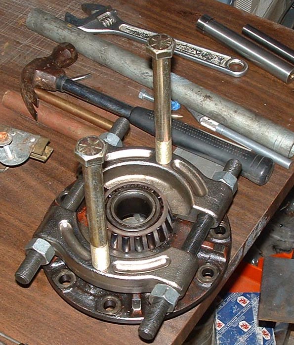
Getting the old bearings out was not something I could handle. But with some major help from Dick Vandermeyden, we got them all off. Dick had to make a special puller which was the combination of the bearing splitter seen here, which was locked under the old roller cone, and a machined aluminum block which went between the bolts. After the block was bolted down, Dick put a hydraulic micro jack between the aluminum block and the center shaft on the plate, and pressed the bearing off 1/4" inch at a time. All of the other bearings and races came off with a standard press and no special tooling.
Stripping the non syncro Moss manual transmission went pretty smoothly. No special tools or pressing was required! I'll powder coat the case and repaint the interior with Glyptol. On the bell housing it will just get a good cleaning and polishing. The seals were worn out on both ends of the main shaft, but otherwise it was in pretty good shape.
There are lots of parts involved with any transmission, all of which need to be cleaned and inspected for unnatural wear or damage. Luckily everything was in pretty good shape, I bought new main shaft bearings, but found that the new replacement bearings had more slop in them than the originals so I decided to just reuse all the original bearings and take my chances. The seals and gasket sets are available from "the usual's" along with rubber shift bushings and other small bits you may loose in the rebuild process, watch out for flying springs, roller balls and pistons, in the syncro gears.
Here are the needle bearings and oil pump plates for the lay shaft. The lay shaft is a single unit an must be lowered into the bottom of the case before putting the main shaft in. After the main shaft is in place the lay shaft is lifted up into place.
Here is a shot of the lay shaft. The needle bearings fit inside and are then held in place by the shaft. The shop manual recommends using a dummy shaft to install the lay shaft but several people I've talked to say its not that hard to install without the dummy shaft, so I'll give it a whirl.
The main shaft and a couple of the syncro rings laying around. One of the main shaft bearings is in the background. and parts of the shifter linkage is in front. Its all fairly straight forward "40s" technology, but only goes together one way. Thank goodness for the shop manual.
I only stripped the transmission top and shifting unit down to this point. It was all working perfectly and really just needed a good cleaning. I installed new safety wires on all the shift fork bolts along with lock tight, just to be sure everything stays put.
Here is the shifter linkage housing which bolts on the transmission top. It was bead blasted and wire wheeled then rebuilt. I used most of the original parts, very little wear, and most parts are impossible to find new.
This is the rear plate where the output would come out. Again I bead blasted and polished this, then installed new seals and gaskets. This unit also holds the speedo gear drive, and the rear transmission mount. This car #888082 was one of the first cars to have the single pin and spring arrangement for transmission mounting.
That is it for this page, guess what gets ripped apart next!